Post by digimon on Oct 31, 2008 10:40:16 GMT 8
This Post Original Provide By DAVE AKA PSYCHED
VECS DIY KING !
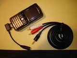
Hey there guys .. as promised once upon a time .. my sharing on how to add an AUX port to your Pioneer players so that you can hook up almost anything to your car speakers through a simple input jack ... this hack serves to replace the Pioneer RB10 or RB20 IP Bus extension (as in picture below) which will cost you a BOMB to buy in Malaysia (i no need to elaborate on what it will cost in Kuching lah ...) ... so enjoy and happy trying to those who find it useful ...

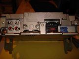
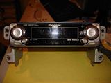
If you already have a CD changer that is connected to your headunit via IP-BUS, you can still use this hack.
Simply splice into the cable, determine which wires go to pins 7, 9, 10, and 11, and splice into them to add the new audio-in plugs of your choice.
In this example, I use female RCA jacks from a cable that came with a VCR or stereo once upon a time.
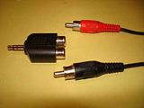
Alternatively, you can use a 1/8" (3.5mm) mini stereo connector, if you plan to use only with devices that have a 1/8" audio jack.
I used these wires and connectors that attatch power and reset switches and LEDs to almost all computer motherboards.
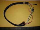
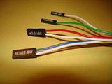
They are perfectly spaced to fit over the pins of the IP-Bus socket.
You should be able to get these from a local computer build/repair shop.
I'm sure they will have some laying around that you can have, probably for free.
All you really need is (1) 3-4 wire connector and (1) 1-2 wire connector.
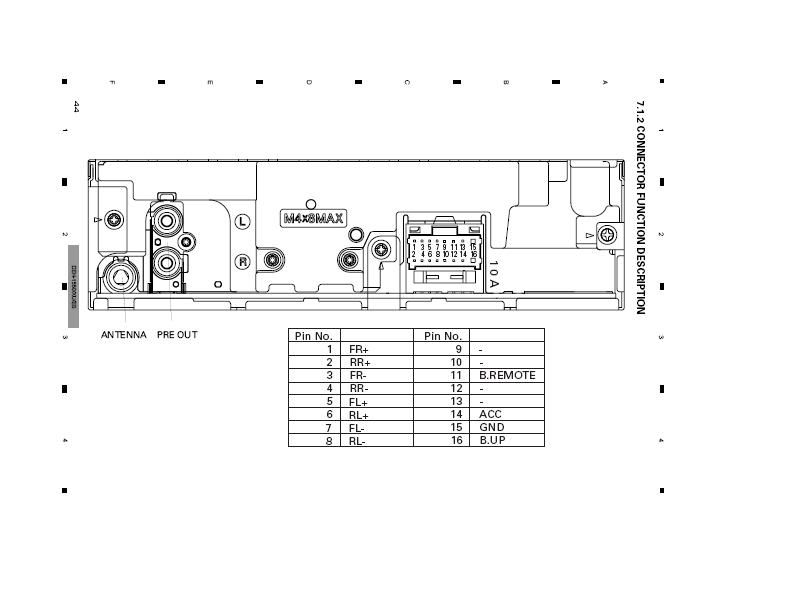
Using this pin-out schematic, locate your pins.

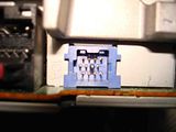

It's easy to move the wires around if you need to fill empty slots in the connectors. Use a very small screwdriver, pin, or similar to gently lift the little tab that holds the connector in place and slide the wire out.
Some of the tabs break easily, and you'll need to have them in their original position to hold the wires in when you reinsert them, so be careful.

Assuming you already have your female RCAs, you may want to connect and solder them before you reinsert the wire clips into the plastic connectors, especially if you plan on using heat-shrink sleeves.
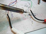
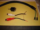
Make sure you wire the +/- wires correctly.
On an RCA, the center is + and the outer collar is -Ground, red is usually the right channel, and white the left channel.
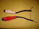
On a 1/8" (3.5mm) jack, the tip is +L, the ring (closest to the tip) is +R, and the sleeve is -Ground.
These are the usual/traditional configurations.
Now, you can put the 3-4 wire connector onto the 9-10-11 pins. It is a snug fit.
And push the 1-2 wire connector onto the 7 pin. If you have a 2 wire connector, the empty slot can be pushed onto the 3 or 4 pin. I found the 3 pin to be a snugger fit.
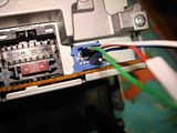
Now you can band the connectors together with a zip-tie.
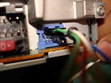
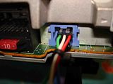
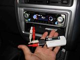
Now enjoy your virtually free DIY IP-Bus adapter!
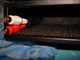
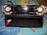
In order to listen to external devices attached to this connector, you must first enable the "AUX" option on the headunit.
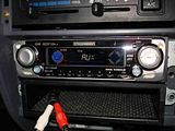
Consult the manual for your unit for details (Pioneer online manuals - www.pioneerelectronics.com/pna/product/manual/0,,2076_4277,00.html).
On my headunit, I have to turn the unit off, press and hold the function (F) button for 3 seconds, use the up or down arrows to navigate to the AUX on/off option, select "ON", then turn the unit on again. Then when I press Source on the headunit, AUX will be one of the options.
What you want to hook up to ure new IP BUs cable next is up to your imagination ... hope you enjoy ...


This Post Original Provide By DAVE AKA PSYCHED
VECS DIY KING !
VECS DIY KING !
Hey there guys .. as promised once upon a time .. my sharing on how to add an AUX port to your Pioneer players so that you can hook up almost anything to your car speakers through a simple input jack ... this hack serves to replace the Pioneer RB10 or RB20 IP Bus extension (as in picture below) which will cost you a BOMB to buy in Malaysia (i no need to elaborate on what it will cost in Kuching lah ...) ... so enjoy and happy trying to those who find it useful ...


If you already have a CD changer that is connected to your headunit via IP-BUS, you can still use this hack.
Simply splice into the cable, determine which wires go to pins 7, 9, 10, and 11, and splice into them to add the new audio-in plugs of your choice.
In this example, I use female RCA jacks from a cable that came with a VCR or stereo once upon a time.

Alternatively, you can use a 1/8" (3.5mm) mini stereo connector, if you plan to use only with devices that have a 1/8" audio jack.
I used these wires and connectors that attatch power and reset switches and LEDs to almost all computer motherboards.


They are perfectly spaced to fit over the pins of the IP-Bus socket.
You should be able to get these from a local computer build/repair shop.
I'm sure they will have some laying around that you can have, probably for free.
All you really need is (1) 3-4 wire connector and (1) 1-2 wire connector.
Using this pin-out schematic, locate your pins.


It's easy to move the wires around if you need to fill empty slots in the connectors. Use a very small screwdriver, pin, or similar to gently lift the little tab that holds the connector in place and slide the wire out.
Some of the tabs break easily, and you'll need to have them in their original position to hold the wires in when you reinsert them, so be careful.

Assuming you already have your female RCAs, you may want to connect and solder them before you reinsert the wire clips into the plastic connectors, especially if you plan on using heat-shrink sleeves.


Make sure you wire the +/- wires correctly.
On an RCA, the center is + and the outer collar is -Ground, red is usually the right channel, and white the left channel.

On a 1/8" (3.5mm) jack, the tip is +L, the ring (closest to the tip) is +R, and the sleeve is -Ground.
These are the usual/traditional configurations.
Now, you can put the 3-4 wire connector onto the 9-10-11 pins. It is a snug fit.
And push the 1-2 wire connector onto the 7 pin. If you have a 2 wire connector, the empty slot can be pushed onto the 3 or 4 pin. I found the 3 pin to be a snugger fit.

Now you can band the connectors together with a zip-tie.


Now enjoy your virtually free DIY IP-Bus adapter!


In order to listen to external devices attached to this connector, you must first enable the "AUX" option on the headunit.

Consult the manual for your unit for details (Pioneer online manuals - www.pioneerelectronics.com/pna/product/manual/0,,2076_4277,00.html).
On my headunit, I have to turn the unit off, press and hold the function (F) button for 3 seconds, use the up or down arrows to navigate to the AUX on/off option, select "ON", then turn the unit on again. Then when I press Source on the headunit, AUX will be one of the options.
What you want to hook up to ure new IP BUs cable next is up to your imagination ... hope you enjoy ...


This Post Original Provide By DAVE AKA PSYCHED
VECS DIY KING !


